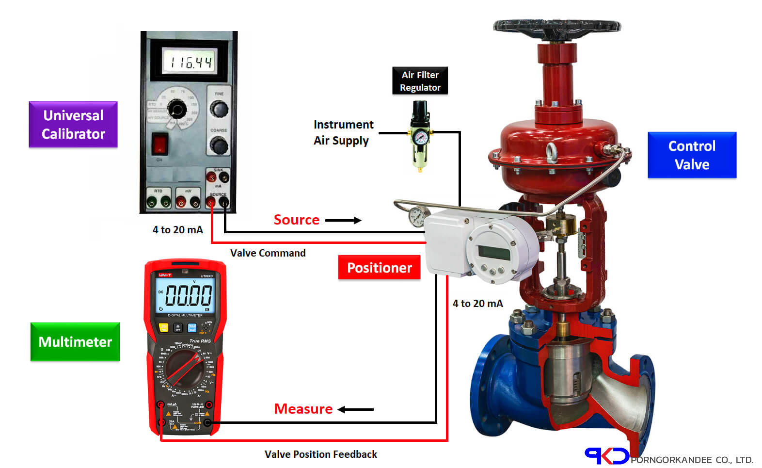

- Assume the valve is a 4-20mA operated pneumatic valve. It also has a 4-20mA valve position feedback output.
- Connect the universal calibrator (or source) to the input of the valve.
- Connect the multimeter at the valve position feedback output as shown in above the setup figure.
- Select the Source function in universal calibrator and the knob will help to vary the mA (4 to 20mA).
- Select 4mA in the calibrator (also called as source meter). The control valvewill show a 0% valve position. We can verify the valve position on the scale provided on the control valve.
Also, the valve has 4 – 20mA output which indicates valve position feedback. We connected a multimeter to measure this valve position feedback. The valve position feedback range is 0 to 100 percent which is equivalent to 4 to 20mA. In this case, the multimeter will show 4mA.
- Now increase the current (mA) in the calibrator from 4mA to 8mA. Now the valve will travel from 0% to 25%. The multimeter will show 8mA valve travel position feedback (25%).
- Now increase the current (mA) in the calibrator from 8mA to 12mA. Now the valve will travel from 25% to 50%. The multimeterwill show 12mA valve travel position feedback (50%).
- Now increase the current (mA) in the calibrator from 12mA to 16mA. Now the valve will travel from 50% to 75%. The multimeter will show 16mA valve travel position feedback (75%).
- Now increase the current (mA) in the calibrator from 16mA to 20mA. Now the valve will travel from 75% to 100%. The multimeter will show 20mA valve travelposition feedback (100%).
- Now we tested the control valve from 4mA to 20mA upward direction. Now repeat the same in downward direction i.e. from 20mA to 4mA in steps.
- Note: While sourcing you can view the Feedback on multimeter these will be nearby reading to source mA.
- Now we completed the upward test from 4mA to 20mA. Repeat the same steps in a downward direction also i.e. from 20mA to 4mA in steps.
 We have got authorized to support UNiCHiMA Brand, DAEHAN Sensor, YAMARI Temp. Sensor, ACEZ Sensing, Greentech Innovation, and KOBOLD(Germany). The latest is DEMBRA Controll Valve.
Leave A Comment